


Up: Parent directry
A-Omega calculation on the slit micro-lens
Daigo Tomono
July 26, 2002
Abstract:
On considerations of spectrometer design1, it was made clear that we can
not afford for A enlarged by the sparse core area surrounded by
the cladding layers in the pseudo
slit. Table 1 shows an example of the K-band spectrometer.
The design assumes 50
enlarged by the sparse core area surrounded by
the cladding layers in the pseudo
slit. Table 1 shows an example of the K-band spectrometer.
The design assumes 50  m diameter fiber cores and 100 m
interval to align the fibers, and the 100 m interval is imaged on 2
pixels of the FPA. As this is a paraxial calculation, lens diameter of
the camera optics is practically larger than 290 mm, which is too big to
be really constructed.
m diameter fiber cores and 100 m
interval to align the fibers, and the 100 m interval is imaged on 2
pixels of the FPA. As this is a paraxial calculation, lens diameter of
the camera optics is practically larger than 290 mm, which is too big to
be really constructed.
A micro-lens array on the spectrometer entrance slit is considered here
to minmize the A required for the spectrometer.
Table 1:
An example of K-band spectrometer design
| fiber FOV |
0.2 arcsec |
| N.A. of light |
two times bigger to allow FRD |
| fiber core diameter |
50 m |
| fiber cladding diameter |
100 m |
| resolution power |
4000 |
| grating diffraction order |
2 |
| groove interval |
12.6 m |
| central wavelength |
2.2 m |
| width of a spectral element on FPA |
37 m |
incident angle  |
-4.6 deg |
emergent angle  |
25.4 deg |
| collimator focal length |
1035 mm |
| camera focal length |
382 mm |
| incident beam width |
321 mm |
| grating width |
322 mm |
| emergent beam width |
290 mm |
A micro-lens array is assumed to be attached directly onto the fiber
exits. The fiber has a core radius of  in m, with the
scrambled telescope pupil is imaged on the exit. The micro-lens images
the scrambled telescope focal plane onto an image plane of radius
in m, with the
scrambled telescope pupil is imaged on the exit. The micro-lens images
the scrambled telescope focal plane onto an image plane of radius
 in m, which is the assumed cladding diameter. The
paraxial micro-lens is assumed to be placed
in m, which is the assumed cladding diameter. The
paraxial micro-lens is assumed to be placed  (in m) from the fiber
exit, making the image plane
(in m) from the fiber
exit, making the image plane  (in m) from the lens. Here, effective
focal length of the micro-lens
(in m) from the lens. Here, effective
focal length of the micro-lens  is the same as .
Figure 1 shows the assumed geometry of the fiber core
and the micro-lens. Beam from the core has a light cone angle of
 in the air. Output light cone angle is calculated as
follows for small
in the air. Output light cone angle is calculated as
follows for small  .
.
As a collimated beam is focused onto a single point on the image plane,
can be calculated as
 |
(1) |
The output light cone angle  is calculated tracing light
from upper most point and lower most point on the fiber core going in to
the lens in the same
direction as the optical axis:
is calculated tracing light
from upper most point and lower most point on the fiber core going in to
the lens in the same
direction as the optical axis:
 |
(2) |
Therefore, A at the slit for a collimated beam is
A of a ray on the fiber eixt is the same as on the pseudo
slit.
Figure 1:
Geometry of the fiber exit and the micro-lens
|
|
We have to expand our consideration light from anywhere on the fiber
core. Figure 2 shows that the beam direction
 of the light depends upon the direction of light from
the fiber core.
of the light depends upon the direction of light from
the fiber core.
A ray from the center with maximum divergence from the optical axis goes
through the lens at
 |
(5) |
and reaches the image plane at
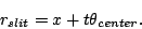 |
(6) |
Therefore,
 |
(7) |
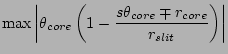
Beam divergence  from the image plane is
Figure 2:
Geometry of the fiber exit and the micro-lens
|
|
When packing the fibers and micro-lens assemblies into the slit, the
micro-lens radius  determines the slit length when it is
bigger than the cladding size and the image size .
From geometry,
determines the slit length when it is
bigger than the cladding size and the image size .
From geometry,
 |
(11) |
and effective radius of the optics  is defined as
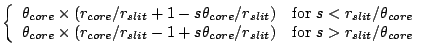
Effective A of the light from the slit imaged by the micro-lens
is calculated from and . Change factor  of
A at the fiber output (A
of
A at the fiber output (A ) and at the slit
(A
) and at the slit
(A ) is defined and calculated as follows:
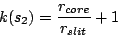
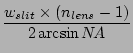
for
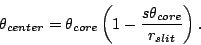
Figure 3 shows the three functions. has two minima at
=  and
and  with the values of
 |
(19) |
and
 |
(20) |
Because is smaller than for our purpose, minimum
value of is at . Therefore, our micro-lens should be designed
so that
 .
.
Figure 3:
Effective A calculated for
 ,
= 25 m, and = 50 m.
,
= 25 m, and = 50 m.
|
|
Practical considerations about effective A
Practically we will have a large number of fibers on the entrance slit.
In the case, change of effective A also depends upon the number
of fibers we have to handle.
When  fibers with core radius and emergent light cone
angle of are considered, simple sum of A of the
light is
fibers with core radius and emergent light cone
angle of are considered, simple sum of A of the
light is
 |
(21) |
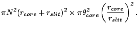
First the fibers with cladding radius  are considered to be
simply lined up on the slit. In the case, we have to extend the
acceptance field of view of the spectrograph. With an on-axis system,
the field of view have to be a circular with a radius of
are considered to be
simply lined up on the slit. In the case, we have to extend the
acceptance field of view of the spectrograph. With an on-axis system,
the field of view have to be a circular with a radius of
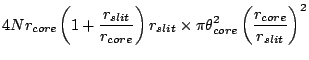
 . In the case effective A of the light that the
spectrograph has to accept is
. In the case effective A of the light that the
spectrograph has to accept is
 |
(22) |
When an off-axis system is designed, the smallest field of view can be a
rectangle of
by . In the case effective
A is
 |
(23) |
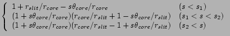
With a micro lens array with
, effective
A of the circular field of view becomes
For the rectangular field case,
Dividing with A changes of effective A are
calculated as in Table 2.
changes of effective A are
calculated as in Table 2.
Table 2:
Change of A at the spectrograph entrance slit.
of fibers with core radius of and cladding radius of
are assumed. For micro lens array a design with
is adopted with radius (half width) of the
imaged slit of .
| |
circular FOV |
rectangular FOV |
| Simple fibers |
 |
 |
| Micro lens |
 |
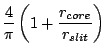 |
It is better to integrate a micro lens array on the
spectrograph entrance slit if the pesudo slit can be wide enough:
 |
(28) |
With typical values of
 and
and
 , should be
 if we are to
integrate a micro lens array.
if we are to
integrate a micro lens array.
Lens design with the smallest effective A
From Equation 20, the spectrometer get smallest effective
A (
 times bigger than the input light)
when
. From Equation 1,
times bigger than the input light)
when
. From Equation 1,
 . Therefore, to minimize effective A,
  in Figures 1 and 2.
From geometry, focal length of the micro lens is the same as ,
and defined by
where is the light cone angle of light in the air
with numerical aperture  we have to accept in the slit width
 .
.
We are thinking of micro lens directly attached to the fiber exit. In the
case, lens length  has to be made longer from according to
its refractive index
has to be made longer from according to
its refractive index  . Therefore,
and from the geometry, the lens surface curvature radius becomes
Moreover, from Equation 11, lens radius becomes
and focal ratio of the lens becomes
with core diameter of
 .
.
Design example
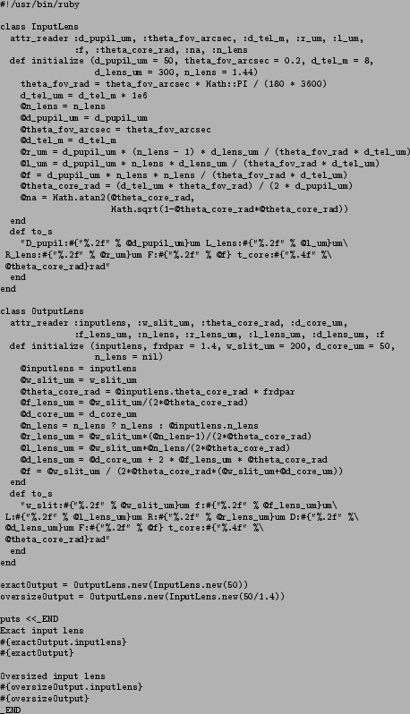
From the equations above, an example of a slit micro-lens is designed.
Parameters are shown in Table 3. Actual calculations are
done in the directory
gin-an:tomono:~/Design02/0508_MicroLens/ with a ruby script shown
in Table 4. A zemax simulation for the design is
shown in Figure 4.
Table 3:
An example of K-band spectrometer design
| Input micro-lens |
Pupil image diameter  |
50/1.4 m |
Fiber FOV  |
0.2 arcsec |
Telescope diameter  |
8 m |
Lens diameter  |
300 m |
| Refractive index |
1.44 |
| Lens length |
1988.98 m |
| Curvature radius |
607.74 m |
| Focal ratio |
9.55 |
| Light cone angle |
0.1086 rad |
| Output micro-lens |
| FRD parameter (output/input cone angle) |
1.4 |
| Pseudo slit width |
200 m |
| Fiber core diameter |
50 m |
| Refractive index |
1.44 |
| Lens length |
947.13 m |
| Curvature radius |
289.40 m |
| Lens diameter |
250 m |
| Focal ratio |
2.63 |
| Light cone angle |
0.1520 rad |
Figure 4:
ZEMAX simulation of the slit micro-lens shown in Table
3
|
|
Table 4:
A ruby script to calculate the micro-lens geometries
 |
- 2002.2.13.
- -
- 2002.5.8.
- -
- Error in Equation 13 corrected
- Section 8 added
- 2002.5.14.
- -
- Section 8 revised
- Section 8.1 added
- 2002.7.25.
- -
A-Omega calculation on the slit micro-lens
This document was generated using the
LaTeX2HTML translator Version 2K.1beta (1.52)
Copyright © 1993, 1994, 1995, 1996,
Nikos Drakos,
Computer Based Learning Unit, University of Leeds.
Copyright © 1997, 1998, 1999,
Ross Moore,
Mathematics Department, Macquarie University, Sydney.
The command line arguments were:
latex2html -dir html -mkdir -image_type png -local_icons -split 0 -up_url .. -up_title 'Parent directry' slitlens.tex
The translation was initiated by Daigo Tomono on 2002-07-26
Footnotes
- ... design1
- e.g.
tomono@gin-an:/Design01/011229_K_Spec
Up: Parent directry
Daigo Tomono
2002-07-26


![\includegraphics[width=0.75\textwidth]{centerbeam.eps}](img33.png)
![\includegraphics[width=0.75\textwidth]{sidebeam.eps}](img43.png)
![\includegraphics[width=0.75\textwidth]{effaom.eps}](img66.png)